Building a Sega Genesis to Amiga Gamepad Adapter
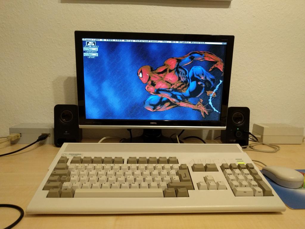
We love retro computing. Especially the Commodore Amiga is great device with lots of games. Each of them can be enjoyed on an emulator, but I prefer real hardware. Unfortunatly, 30 years old joysticks tend to malfunction. Furthermore, it is more comfortable to use a gamepad. Therefore, I was searching for a new gamepad which can be connected to my Amiga. I had something in mind like a CD32 gamepad replica but did not find anything comparable. Instead, I saw lots of new Sega Genesis gamepads on popular online market places and bought one of them. It did not work as expected and I had to build a programmable Arduino based adapter (with some nice additional features:). The results are described in this blog post.
Sega Genesis gamepads and Commodore Amigas game ports use DE-9 connectors. Furtheremore, they are almost pin compatible. I did not dive deeper into the schematics, simply trusted this information and plugged my new Genesis controller into my Amiga. Later, I found out this is rather carelessly because a C64 (which is also almost pin compatible;) could have been damaged. My Amiga seemed ok but the gamepad did not work properly. It was possible to play games but after seconds or minutes buttons like "Up" or "Down" stopped working. Therefore, it was necessary to verify the Genesis and Amiga pin layouts. A good description can be found in the Amiga Hardware Reference Manual and this blog entry. Results look like this:
| Pin | Sega Gamepad Select=HIGH | Sega Gamepad Select=LOW | Amiga Joystick Port |
|---|---|---|---|
| 1 | Up (OUT) | - | Up (IN) |
| 2 | Down (OUT) | - | Down (IN) |
| 3 | Left (OUT) | Gnd | Left (IN) |
| 4 | Right (OUT) | Gnd | Right (IN) |
| 5 | +5V (IN) | +5V (IN) | - |
| 6 | B (OUT) | A (OUT) | Button-1 (IN) |
| 7 | Select Signal (IN) | Select Signal (IN) | +5V (OUT) |
| 8 | Gnd | Gnd | Gnd |
| 9 | C (OUT) | Start (OUT) | Button-2 (IN) |
Sega Genesis Gamepad: Classic Genesis controllers come with three fire buttons (A, B, C), Start and a four directional D-pad. Including Vcc and Gnd, 10 pins would have been necessary. To overcome this problem, Sega added a Select signal and a multiplexer. Depending on the Select state (High or Low), certain gamepad elements write their output to the corresponding output pins. Left and Right are pulled to Ground when Select is set to low. This allows a console to verify whether a gamepad is connected because a user could not press left and right simultaneously. Sega also produced gamepads with six fire buttons. In this case, the controller contains a state machine which is controlled by the select signal as well. Again, read here for details.
Amiga Joystick Port: Compared to the Genesis, Amiga Joysticks are simple. Left, right, up, down and one or two fire buttons are directly connected to the game port pins. One important aspect is the direction: Software can configure whether pin 5, 6 and 9 are input or output signals. A classic joystick needs a game port with input pins only. More complex devices like CD32 gamepads (which are not in the scope of this article) contain a shift register and the Amiga has to output some kind of clock signal for controlling them.
My Sega gamepad replica is a six button device. If you take a look at the table above, this leads to two problems:
- The gamepad signal pin is connected to Vcc. The state machine remains in its initial state. Therefore, only fire button B and C are available.
- Amiga joystick port pin 5 is undefined and connected to Vcc of the Genesis gamepad. If it is programmed by software as an high output pin, everything is fine. Otherwise, the internal state machine chip could malfunction.
Reconsidering my problems from above (up and down did not work anymore after a certain amount of time), the gamepad state machine is not working correctly. Maybe because some games configure pin 5 as an input pin, maybe for some reason I am not aware of. Therefore, I decided to build my own arduino based genesis to amiga adapter. This approach has the following advantages:
- Each pin is mapped correctly and we can be sure gamepads pin 5 is connected to Vcc, no matter what the Amiga game port pin configuration looks like.
- Our arduino can drive the select signal in the correct way. Due to this, the controllers state machine is executed and six fire buttons are available. Two can be used by games, the four remaining ones for special actions like auto fire.
My adapter consists of three components: A "do it yourself" plastic case, an Arduino Leonardo and an empty shield like this. The final result looks like this:
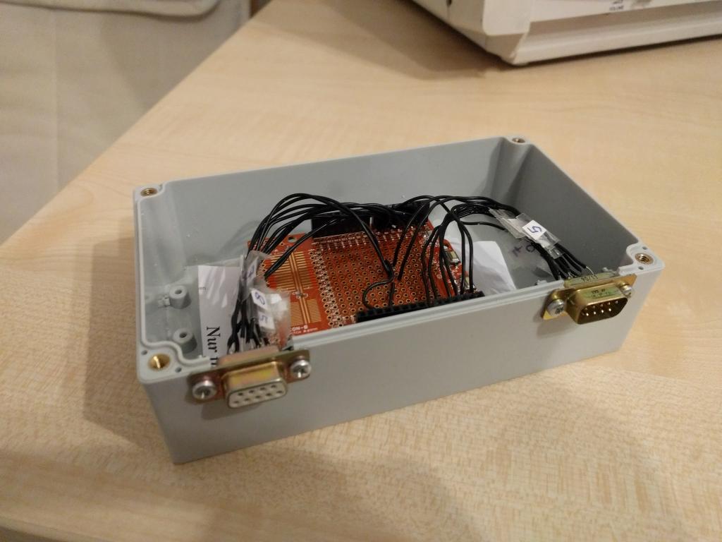
The shield sits on top of the Arduino. Two DE-9 connectors are soldered on the shields prototyping area. I have cut two holes in the plastic case and laid the DE-9 connectors into them. Four screws stabilize the whole design. The software is available on Github. I soldered the genesis gamepad pins to A0, A1, A2, A3, A4, A5 and 7 of the Arduino. The Amiga is connected with digital 0, 1, 2, 3, 4, 5 and 6 (besides Vcc and Gnd). Basically, you can chose every programmable Arduino port. I am using the previously described pins because the soldering process was more comfortable this way ;).
My Arduino software has three config options which can be activated during compile time:
- Serial Output: Write debug information (ASCII characters) to the Arduino serial port. This allows us the check with a serial console whether everything works correctly.
- Led Output: The Arduino LED flashes when a Genesis button is pressed. Another debug option.
- Pin Output: Set the Amiga game port pins to high or low when a button is pressed. This is what you want for a working adapter so it should not be disabled.
My Arduino sketch performs the following algorithm: The Sega gamepad is read 60 times per seconds. This is necessary because an Amiga game checks the joystick buttons 50 times (PAL) or 60 times (NTSC) per second as well. Each iteration, the select signal is used to execute the gamepad statemachine. The results are written to the Amiga game port. I have implemented the following features:
- D-pad: Left, right, up and down are directly forwared to the Amiga.
- Fire: A and B are used as fire button 1 and 2 on the Amiga.
- X performs auto fire.
- Y emulates an infinite loop of left, right, left, right, etc. This can be used for these joystick killers like "aquatic games", "winter games", etc.
- The Mode button activates a special emulation: B does not trigger fire 2 anymore. Instead, B performs Up. This way, one-button "jump and run" games which use Up to jump can be played much more comfortable.
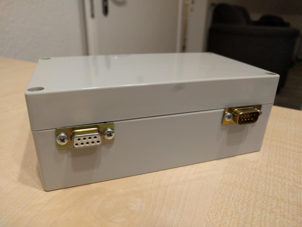
The final result can be seen on the following image. The Genesis to Amiga dapater is on the left side and looks a little bit like the AC adapter on the right: